Saturday 18 June 2016

Automatic Railway-Level crossing control system

Automatic Railway-Level crossing control system 

Normally at Railway level crossing a person has to keep track of trains its arrival and departure at those junctions accordingly he has to block external traffic. Being the most tedious and hectic job person has to be alert and accordingly he has to take necessary action. This project helps in automating this tedious process.
  IR Sensor can be used to detect objects it has three pins
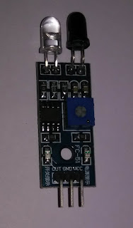
1. Vcc -connect it to 5v
2. Gnd- connect it to ground
3. Out is digital o/p will give logic 1 on obstruction else logic 0

IR sensor has to be placed at a distance from level crossing in such a way that
whenever rail approaches level -crossing IR sensor has to be obstructed by train immediately this has to give warning to people who are about to cross junction. As well as it has to control gate indirectly which is controlled through motor. 


Download - code

Gas Sensor Based Automation

Gas Sensor Based Automation 

Fire Alarm systems can be used to alert people just at the instance of occurrence of Fire accident. Particularly if fire accident is due to LPG gas or Marsh gas or Methane (CH4) then this project can be used to alert people on leakage of gas.


Sensor Has 4 pins 
1. Vcc should be connected to 5v
2. Gnd should be connected to 0v
3. AO Analog should be connected to ADC input
4. DO If Analog o/p is used then not required other wise it gives Digital output Logic 1 when gas is
 detected

Sensor detects Methane gas CH4 if present in air and gives equivalent analog voltage proportional to concentration of CH4 gas.

In this experiment a cotton piece is dipped in rectified spirit and placed near sensor to show how it produces analog output for 10bit ADC values are shown on LCD with appropriate message

1. If  Sensor output is below 500 then considered as safe
2. if it reads between 600 to 900 considered as critical 
3. if it reads above 900 considered as danger immediate attention is required

                                                                Download - code


Saturday 11 June 2016

Automation Using GSM

Automation Using GSM

In Earlier post (Notice Board Display using GSM) I covered how to configure GSM module using AT commands similarly for Automation using GSM also similar operation is required.
use USB to TTL converter to create virtual com on your PC then connect your GSM module to USB to TTL converter and communicate with it using coolterm.

                                          USB-TTL converter


                                              USB-TTL -GSM interface
                                      1.Tx of USB-TTL to Rx of GSM
                                      2. Rx of USB-TTL to Tx of GSM
                                      3 Gnd to Gnd

                              1) Type AT it should respond with OK


                               2) Send AT+CMGL="REC UNREAD"
                                    it should respond with ok
                                   send AT +CMGF=1                       //text format
                                          again it responds with ok
                                    send AT+CMGD=1                      //delete message from location 1
                                          again it responds with ok
  

4) wait until it responds with call ready


                                 5) when new message is received it responds with +CMGI: "SM", 1
                                       //location 1 on SIM
                                    then send AT+CMGR=1
                                         //to read message


6) Based on character received you can perform switching action
Here in this example i controlled port 0_8, 0_9 pins based on char 'a' 'b' received
i) toggle LED 0_8 on char 'a'
ii) toggle LED 0_9 on char 'b'


                                                                                     download-code


Saturday 4 June 2016

Automatic Irrigation System using Soil Moisture Sensor

Automatic Irrigation System using Soil Moisture Sensor

Indian Economy mainly depends on Agriculture(Primary sector). Irrigation being the occupation of most of Indian families they still rely on seasonal rains and under-ground water.As cultivation is the most tedious process which requires constant monitoring and maintenance particularly timely watering of plants. 

Watering plants means providing sufficient amount of water but what is the sufficient amount ?, When to water?   Till how much time water-motor should be on? these are the three issues which normal formal will not bother as they fix some schedule and accordingly they will follow. So he may not follow efficient water conservation techniques which may have direct impact on outcome.

This project can be used to address above mentioned issues. timely-sufficient  watering of plants in an automated way. Consequence  will be good yield with economy in terms of water and electricity .


Soil-Sensor can has Four terminals 
Vcc- Connect it to 5V
Gnd- Connect it to 0V
Digital-Output - Connect to any GPIO Pin or
Analog -Output- Connect to any ADC channel

Here i used Analog Output which gives following readings (10-bit ADC)
1.When Not inserted in soil-1023
2.When inserted in dry soil  900<output<1023(drought)
3 When inserted in soil with adequate water  500<output<900(Normal)
4. When inserted in soil with excess water output<500(wet)


download-code

Automatic Water-Level Indicator using Water sensor

Automatic Water-Level Indicator using Water sensor

Water is the most precious resource essential for all living beings. Water used to be renewable resource in the past but now its no more renewable source. Everyone should take it as responsibility to conserve water and save it for future needs.

Water Motors are common in every home generally someone has to monitor until water tank is completely filled sometimes if they forget to turn it off water will be wasted . This project can be utilized to automate this process.


 water-level sensor has three pins
Vcc- connect it to 5V
Gnd- Connect it to 0V
signal-Water level indicator if more than 900 units of (10bit ADC)- tank full 
           else Not full


download-code

Obstacle Detection Using Ultrasonic Sensor

Obstacle Detection Using Ultrasonic Sensor


Ultrasonic Sensor works on the principle of Transmitting Ultrasonic signal of(44Khz) and waits for echo on hearing echo, range of target or obstacle can be calculated as 
Range =(Speed of Ultrasonic wave * echo duration)/2

Speed of Ultrasonic wave = 340m/s
if echo received is in microseconds then effective formula of range reduces to
Range =((17* t(usec))/1000)  (in cm)

Ultra-Sonic Sensor has 4 pins(HC-SR04)
1.Vcc : connect to 5V
2.Trigger: Turn it on for only 10usec (input to sensor)
3.Echo: calculate on-time in usec (output of sensor)
4.Gnd: connect to 0v


download-code


Friday 3 June 2016

Digital Clock using Timer

Digital Clock using Timer

Timer is a Hardware circuit used to measure regular clock pulses.Timer can be used to generate appropriate (known) amount of delay. Timer can be used to create Digital clock. 
Programming Timer requires knowledge of its internal registers.
Prescaler Register (PR): To set division factor of clk
Prescaler : Divides clock by PR+1
Timer Control Register: To control Operation of Timer
Timer/Counter: 32 bit up counter increments for every (PR+1) clk cycles.
Match Control Register: To set one of three possible operations on Match (1.Stop Timer, 2. Generate Interrupt, 3. Reset Timer on Match)
Match Register: To set Delay of Timer.
If Timer operates at 9MHz then for 1sec delay values to be loaded into Match Registers is (9000000)

Clock with Seconds which should increment till 59 and then  roleback to zero.
Minutes which should increment till 59 and then  roleback to zero.
Hours which should increment till 23 and then  roleback to zero.


Hardware Timer is made up of set of registers, applied clock is passed through Prescaler 
Prescaler Register (PR): To set division factor of clk
Prescaler : Divides clock by PR+1
Timer Control Register: To control Operation of Timer
Timer/Counter: 32 bit up counter increments for every (PR+1) clk cycles.
Match Control Register: To set one of three possible operations on Match (1.Stop Timer, 2. Generate Interrupt, 3. Reset Timer on Match)
Match Register: To set Delay of Timer.
If Timer operates at 9MHz then for 1sec delay values to be loaded into Match Registers is (9000000)


download code